
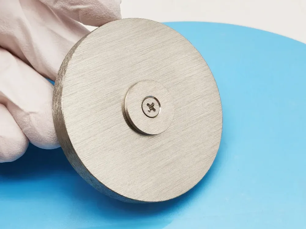
A magnetic keeper replaces traditional mechanical clamps or bolts by using magnetic attraction to hold the target in place. This eliminates clamps or top shields, reduces particulate generation, and speeds target swaps. Mag‑keeper designs also frequently support higher cooling efficiency and more compact cathode layouts.
MetalsTek’s MagKeeper design is one such example that omits clamping rings and uses magnets to secure targets.
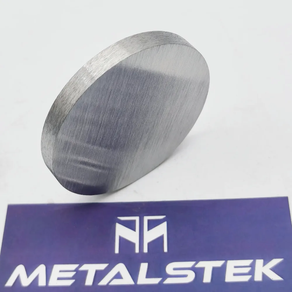
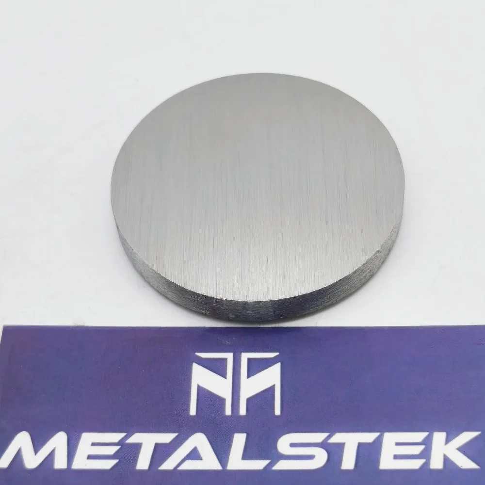
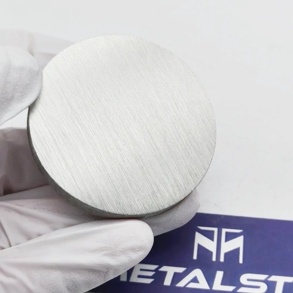
For Sc targets—with proper magnetic circuit design—the magnetic keeper helps maintain stable contact, good heat transfer, and safer operations during high-power sputtering runs. MetalsTek produces high‑purity Sc targets optimized for mag‑keeper designs, offering custom geometries, magnetic circuitry, and thermal performance you can trust.
Key Features & Specifications
Below is an indicative feature table you can refine with your internal measurements:
| Parameter | Typical Range / Detail | Notes & Relevance |
|---|---|---|
| Purity | 99.9 % to 99.999 % | High purity reduces contamination during deposition |
| Size & Geometry | Ø 2″ to Ø 6″ (or custom) | Thickness from 1 mm upward, depending on magnet strength |
| Bonding | Unbonded or bonded to backing plate (Cu, Mo) | Bonding improves thermal conduction for thick targets |
| Magnetic Keeper Mechanism | Surface magnets or magnet ring + keeper plate | Must match magnetic circuit and target material |
| Thermal Load Handling | Up to moderate power densities | Depends on cooling, bonding, and magnetic contact |
| Packaging | Vacuum-sealed or inert-protective | To prevent oxidation or contamination |
| Target Change Time | Rapid – no tools or clamps | Enabled by magnetic keeper mechanism |
These specs are guidelines. Your system’s magnetic field strength, backing plate design, and cooling setup will determine safe power densities and operational limits.
Best Practices & Design Considerations
- Magnet design: The keeper magnet arrangement must create sufficient holding force across the target area without interfering with plasma.
- Backside contact: Ensure that the magnetic contact does not degrade thermal conduction; often a thin conductive interface is used.
- Cooling interface: Use backing plates or cooling wells that align well with the magnetic keeper to maintain temperature stability.
- Thermal expansion: Design for differential expansion between Sc, backing, magnet assembly to avoid stress.
- Material compatibility: Avoid magnetic interference from target or backing metals (use nonmagnetic or magnet-compatible materials).
- Target change protocols: Use safety interlocks so that when magnets disengage, the target release is controlled.
- Vacuum sealing: Mag‑keeper designs often reduce the need for O-rings by employing magnetic retention in hermetic configurations.
You May Also Want to Know
1. What is a magnetic keeper (mag‑keeper) in sputtering?
A magnetic keeper uses magnetic force to hold the sputtering target in place instead of mechanical clamps or bolts. The magnetic field ensures stable contact and allows removal or replacement without tools.
2. Can Sc (Scandium) be used with mag‑keeper systems?
Yes. With proper magnet design and backing interface engineering, Sc targets can be mounted using mag‑keeper systems to leverage their benefits in tool‑free operation.
3. What purity grades are typical for Sc targets?
Typical grades range from 99.9% (3N) to 99.999% (5N). Higher purity reduces contamination risks and supports demanding thin film applications.
4. Which shapes and sizes are common for Sc targets?
Common formats include circular discs (Ø 1″ to Ø 6″ or more), rectangular plates, or custom geometries. Thickness typically starts from ~1 mm and can increase based on cooling or magnetic retention requirements.
5. Should Sc targets be bonded or unbonded in mag‑keeper design?
Both are possible. Unbonded targets simplify the interface but may limit thermal performance. Bonded targets (with Cu or Mo backing) offer better heat removal while retaining magnetic retention when designed correctly.
6. How strong must the magnetic holding force be?
Magnetic holding force must be sufficient to prevent any micro‑movement under plasma pressure or vibration, while not interfering with the plasma or inducing unwanted magnetic fields in the sputtering chamber.
7. What cooling/thermal design is needed with magnetic keeper contacts?
Interface surfaces must be flat and thermally conductive. Thin, conductive coupling layers may be used to ensure consistent thermal contact through magnetic retention. Cooling channels in the backing plate should align with the magnetic mount.
8. Does using a mag‑keeper reduce particulate contamination?
Yes, because it eliminates mechanical clamps and screws, which are common sources of wear, particles, or stray metal fragments in the vacuum environment.
9. Can target changes be done tool‑free?
Yes, that is a core advantage. Magnetic retention lets you detach and reattach the target without tools, speeding maintenance and reducing risk of damaging the mounting hardware.
10. Are there limitations or risks to magnetic keeper designs?
Potential risks include magnetic interference with plasma, thermal contact degradation if surfaces are not well-matched, and misalignment over thermal cycling. Careful magnetic circuit and mounting design are essential.
11. How is the magnetic keeper assembly packaged & aligned?
The magnet components and keeper interfaces are precision aligned during assembly. Protective packaging ensures they remain clean and aligned in transit.
12. What is the lead time for manufacturing Sc + mag‑keeper targets?
Lead time depends on purity, magnet design complexity, and production volume, typically ranging from a few weeks to several weeks.
13. How is purity verified for Sc targets?
Purity is validated via analytic methods such as glow discharge mass spectrometry (GDMS), inductively coupled plasma (ICP) analysis, or comparable high-sensitivity techniques.
14. What are common failure modes in mag‑keeper targets?
Failures can occur from loss of magnetic retention, thermal contact degradation, delamination in bonded layers, cracking under thermal stress, or misalignment under cycling.
15. How to manage expansion, backlash, or misalignment over thermal cycles?
Design tolerances and material selections must account for differential thermal expansion. Preload or flexible interface layers may compensate for shifts over cycling.
16. What safety precautions apply when handling magnetic assemblies with Sc?
Handle magnets carefully to avoid pinching or sudden attraction. Keep magnet pieces away from sensitive electronics. Use gloves and cleanroom tools for Sc to avoid contamination.
17. Can mag‑keeper be retrofitted to existing sputter guns?
In some cases yes, but retrofit requires careful design to match magnetic fields, cooling paths, and mechanical geometry of the existing gun.
18. How does magnetic keeper design influence achievable power density?
If thermal contact is good, mag‑keeper designs can support power densities comparable to clamped targets, but inadequate interface design may limit performance.
19. What materials are safe for backing plates in mag‑keeper systems?
Nonmagnetic metals with good thermal conductivity (Cu, Mo, Al, etc.) are typically used. They must not interfere with magnetic retention but must conduct heat well.
20. How to choose a supplier for magnetic‑keeper compatible Sc targets?
Select a supplier with experience in magnet assembly, tight tolerances, bonding and backing plate design, purity control, and vacuum-compatible packaging.