Why 100 Pieces Were More Demanding Than One Prototype
Engineering Controls Required for Batch Manufacturing
Critical Inspection and Acceptance Points
Three-Week Project Workflow
Packaging Thin-Wall Tantalum Components
Project Significance and Engineering Lessons
Frequently Asked Questions
Related Resources and Products
Project Background
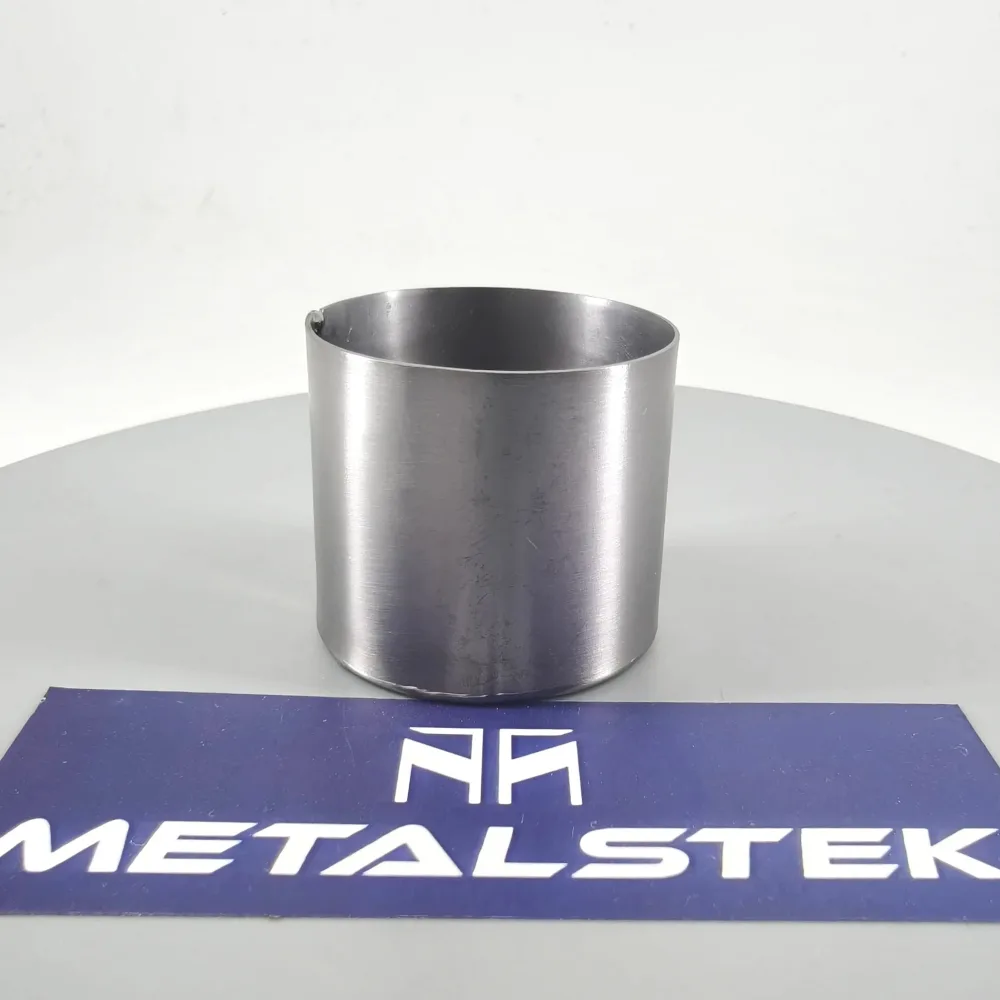
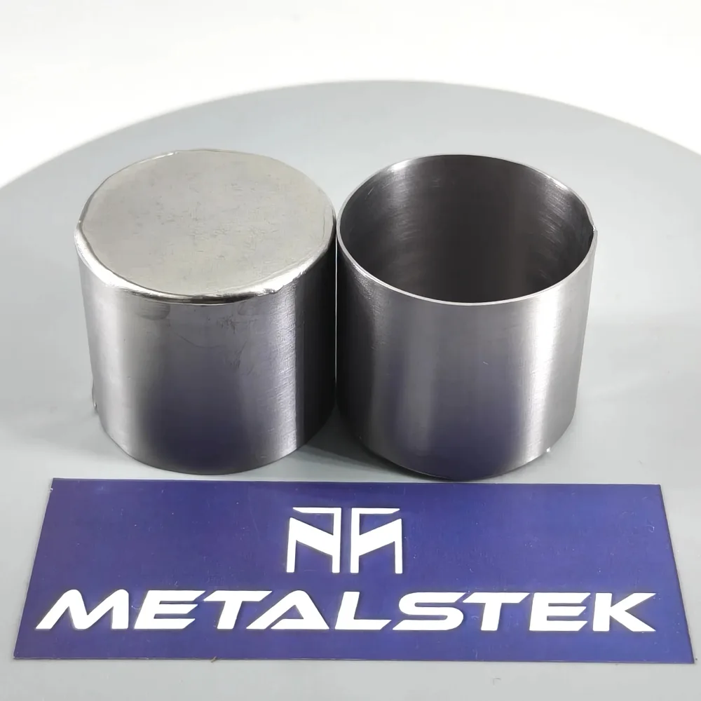
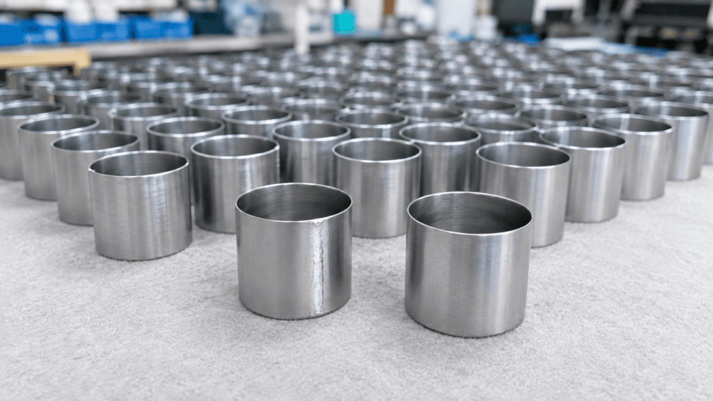
A CNRS-affiliated French earth sciences research laboratory required 100 custom thin-wall tantalum crucibles for laboratory high-temperature experiments and materials research.
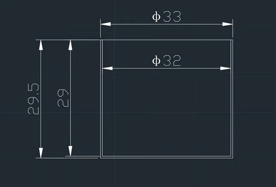
The laboratory needed each crucible to be manufactured from high-purity tantalum according to a common engineering drawing. The specified geometry included a nominal outer diameter of 33 mm, an inner diameter of 32 mm, an overall height of 29.5 mm, an inner height of 29 mm, and a nominal wall thickness of only 0.5 mm.
Customer confidentiality was an important part of the project. The name of the laboratory, its personnel, project number, experimental program, and other identifying information are not disclosed in this case study.
The public project description is therefore limited to information relevant to the engineering challenge:
The customer was a French earth sciences research laboratory affiliated with CNRS.
The material was specified as high-purity tantalum.
The nominal wall thickness was 0.5 mm.
The crucibles were intended for laboratory high-temperature experiments and materials research.
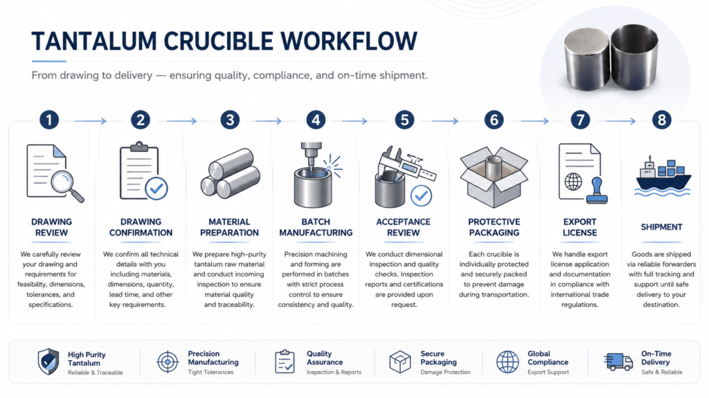
The workflow from engineering drawing preparation through manufacturing and export-license processing took approximately three weeks.
This was not simply a request to determine whether one thin-wall tantalum component could be made. The laboratory required a complete production batch manufactured to the same drawing.
That distinction defined the real value of the project:
Unlike prototype fabrication, this project involved 100 thin-wall tantalum crucibles manufactured to the same engineering drawing, making dimensional consistency, weld quality, and process repeatability just as important as producing one acceptable welded component.
For a research customer, consistency between individual crucibles may be important for fixture compatibility, usable internal space, sample loading, furnace positioning, and the repeatability of experimental conditions. The manufacturing challenge therefore extended beyond material selection or welding feasibility alone.
Project Specifications
Parameter
Project Requirement
Engineering Relevance
Customer type
CNRS-affiliated French earth sciences research laboratory
Required confidentiality and research-oriented project control
Product
Thin-wall welded tantalum crucible
Combined sheet forming, welding, dimensional control, and careful handling
Quantity
100 pieces
Required repeatability across a batch rather than one-off fabrication
Material
High-purity tantalum
Material identity and cleanliness were important for research use
Outer diameter
33 mm
Sensitive to forming variation and weld shrinkage
Inner diameter
32 mm
Closely linked to the specified wall geometry and usable internal space
Overall height
29.5 mm
Required control through forming and assembly
Inner height
29 mm
Defined the required internal geometry
Nominal wall thickness
0.5 mm
Increased sensitivity to deformation, heat, clamping, measurement, and packaging
Construction
Welded fabrication according to the approved drawing
Required controlled joint preparation and repeatable assembly
Intended use
High-temperature laboratory experiments and materials research
Required compatibility review by the laboratory for its specific atmosphere and sample
Public purity value
Not disclosed
A numerical purity should only be published when supported by the applicable material certificate
Project cycle
Approximately three weeks
Included drawing preparation, production, and export-license processing
The dimensional relationship is important. The difference between the specified outer and inner diameters is only 1 mm, corresponding to a nominal 0.5 mm wall on each side.
This left limited room for uncontrolled deformation. A small change in forming, joint alignment, weld shrinkage, or measurement method could have a visible effect on diameter or roundness.
The crucibles were therefore better understood as precision thin-sheet fabrications than as conventional heavy-wall machined containers.
Why High-Purity Tantalum Was Suitable
Tantalum is a refractory metal valued for its high melting point, low vapor pressure, corrosion resistance, and useful ductility. Its formability makes it suitable for thin-sheet components and complex fabricated geometries that would be difficult to produce from more brittle refractory materials.
ASTM B708 covers tantalum and tantalum-alloy plate, sheet, and strip. However, a public case study should not claim compliance with a particular grade, purity, or standard unless that requirement is supported by the project drawing, purchase order, or material certificate.
For that reason, this article uses the verified project description high-purity tantalum without assigning an unsupported percentage or UNS grade.
Tantalum’s high-temperature capability must also be understood correctly. At elevated temperatures, the metal becomes increasingly sensitive to oxygen and other atmospheric gases. The customer must therefore evaluate the operating atmosphere, temperature, duration, sample chemistry, and compatibility with surrounding furnace components for the intended experiment.
The crucible material alone does not guarantee suitability for every high-temperature environment.
Why the 0.5 mm Wall Made the Project Difficult
1. Low Structural Stiffness Before Final Assembly
A 0.5 mm cylindrical wall has limited resistance to local pressure.
During cutting, forming, assembly, welding, measurement, cleaning, and packaging, relatively small forces can influence:
Diameter
Roundness
Edge alignment
Wall straightness
Local flatness
Opening geometry
A thicker machined crucible can often tolerate normal clamping and handling forces without a measurable change in geometry. A thin-wall component requires a different approach.
The part must be supported without crushing it, held without introducing dents, and measured without allowing the inspection tool itself to distort the wall.
2. Forming Accuracy Directly Affected Weld Fit-Up
The edges of a fabricated crucible must reach the welding stage in a stable and repeatable position.
If the formed diameter changes between parts, the joint may arrive with:
A wider or narrower gap
Misaligned edges
Local overlap
Uneven contact
Different springback
Different restraint inside the fixture
These variations can alter how heat moves through the joint and how the molten region behaves.
For a 100-piece batch, the welding operation cannot reasonably compensate for a different pre-weld geometry on every component. Repeatable welding begins with repeatable blank preparation and forming.
3. The Welding Window Was Narrow
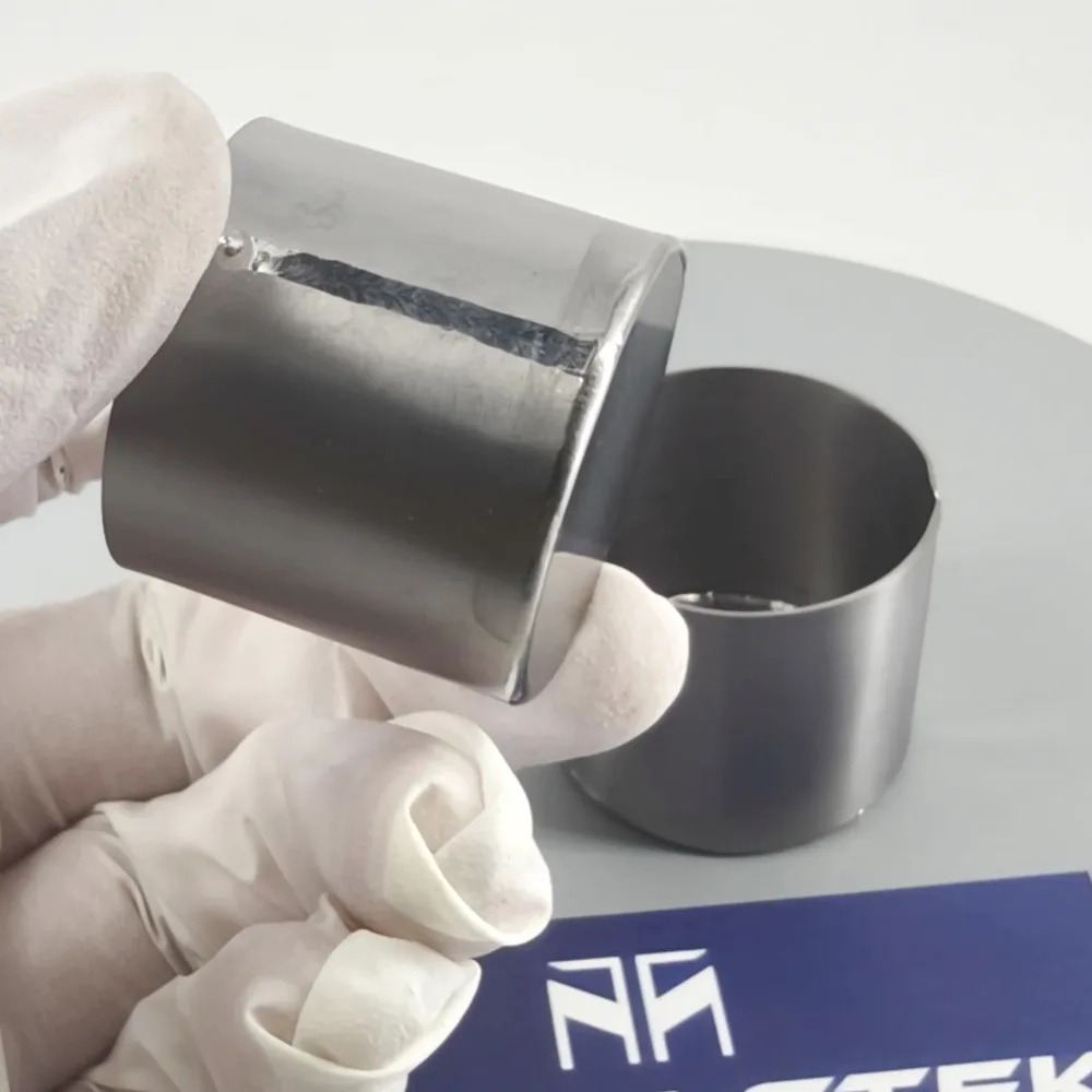
The joint required enough heat to establish continuity, but too much local heat could damage the 0.5 mm material.
Potential risks associated with thin tantalum welding include:
Incomplete fusion
Burn-through
Edge collapse
Excessive weld width
Local thinning
Distortion
Enlargement of the heat-affected zone
Published research has demonstrated TIG welding of 0.6 mm tantalum sheet and documented oxidation differences within the joint where shielding conditions varied. The research supports the general engineering concern that thin tantalum welding requires close control of both heat input and atmospheric protection. It does not establish the exact process used for this commercial project.
The public case study therefore does not disclose or invent welding current, voltage, speed, gas flow, fixture design, filler-metal use, or other process-specific parameters.
4. Weld Shrinkage Could Affect Geometry
When a localized welded region cools, contraction can influence the surrounding thin wall.
Possible dimensional effects include:
Reduced diameter near the joint
Local flattening
Ovality
Edge pulling
Changes in base alignment
Changes in overall height
Instability on a flat surface
A visually continuous weld does not automatically mean that the completed crucible remains geometrically acceptable.
For this reason, weld appearance and final dimensions must be treated as separate acceptance considerations.
5. Hot Tantalum Required Protection from Atmospheric Contamination
Tantalum can be welded, but its behavior at welding temperatures makes cleanliness and shielding important.
Research comparing TIG- and electron-beam-welded tantalum has examined the effects of oxygen, nitrogen, hydrogen, and air contamination on welded joints. Another study of 0.6 mm tantalum sheet found differences in oxidation across the weld and heat-affected areas.
These findings support several general engineering principles:
Joint surfaces should be clean before welding.
Heated material should be protected from atmospheric exposure.
Protection may need to extend beyond the visible molten pool.
The cooling region may remain sensitive after the heat source moves away.
Shielding design should match the actual joint geometry and qualified welding procedure.
These are engineering requirements associated with tantalum welding. They should not be presented as project-specific process details unless verified by manufacturing records.
6. The Finished Parts Remained Vulnerable
Completing the weld did not remove the risk of dimensional damage.
Thin-wall crucibles could still be affected by:
Stacking pressure
Uncontrolled hand pressure
Abrasion between parts
Impact during transport
Inadequate internal support
Compression inside the shipping package
Packaging was therefore connected to manufacturing quality. A component that meets its dimensional requirement before packing can still arrive distorted if the packaging transfers load directly to an unsupported 0.5 mm wall.
The Real Challenge: 100 Pieces, Not One Prototype
Producing one acceptable part and manufacturing 100 parts to the same engineering drawing are not equivalent achievements.
A prototype may receive:
Additional manual adjustment
Repeated trial fitting
Individual welding corrections
Extra dimensional correction
Longer inspection time
One-off operator decisions
That approach may succeed for a single component but become unstable when repeated across a production batch.
For 100 thin-wall tantalum crucibles, variation could accumulate through a chain of connected operations:
A change in one stage could appear as a problem later.
For example:
A different blank width could change the formed circumference.
A changed circumference could alter the joint gap.
A changed gap could influence weld behavior.
Changed weld behavior could affect diameter and roundness.
A geometrically acceptable part could still be damaged by unsuitable packaging.
This is why the project should not be presented simply as “welding tantalum crucibles.”
Its greater engineering significance was the need to control an interconnected process across a 100-piece order.
One acceptable prototype demonstrates that a component may be manufacturable. A consistent batch demonstrates whether the manufacturing route is repeatable.
Engineering Controls Required for Batch Manufacturing
Because detailed manufacturing records are not reproduced in this public case study, the following section explains the engineering controls the project required rather than claiming undisclosed machines, parameters, or inspection results.
1. Drawing and Acceptance Review
The manufacturing plan had to begin with a common interpretation of the drawing.
Critical questions included:
Which dimensions were final acceptance dimensions?
Where should OD and ID be measured?
Was roundness subject to a separate limit?
How was the welded structure defined?
Was the 0.5 mm value nominal or subject to a specific tolerance?
Were the wall and bottom made from the same thickness?
Which surface conditions were acceptable?
What documentation was required?
Were any test methods required beyond visual and dimensional review?
Without agreed answers, a manufacturer and customer may interpret the same drawing differently.
For a 100-piece batch, drawing revision control is especially important. All parts must be manufactured against the same approved version.
2. Material Identity and Cleanliness
The raw material needed to correspond to the agreed tantalum requirement.
Before an order is released, the manufacturer and customer should define:
Tantalum grade or purity
Applicable material standard, when required
Critical impurity limits
Material certificate requirements
Sheet thickness and tolerance
Surface condition
Cleaning requirements
Traceability requirements
“High purity” is not a complete purchasing specification by itself. A numerical purity, impurity basis, test method, and required document should be stated when they are critical to the experiment.
Clean handling is also important. Oil, dirt, embedded particles, and residues near a heated joint can undermine the purpose of selecting high-purity material.
3. Repeatable Blank Preparation and Forming
The formed body must provide a consistent starting condition for welding.
Important variables include:
Blank length and width
Edge straightness
Burr condition
Rolling or forming sequence
Springback
Pre-weld diameter
Edge alignment
Joint-gap consistency
The objective is not merely to make each blank look cylindrical. The objective is to produce similar pre-weld geometry across the batch.
When the wall is only 0.5 mm, repeated manual reshaping may introduce local work hardening, waviness, or different springback between parts. The forming route should therefore minimize unnecessary correction.
4. Stable Positioning and Weld-Process Control
Thin cylindrical parts require controlled positioning during welding.
A suitable production approach must manage:
Joint location
Edge alignment
Component restraint
Heat accumulation
Weld progression
Shielding coverage
Movement during cooling
Repeatability between pieces
The fixture or positioning method should support the part without crushing or marking the thin wall.
The welding process must also provide enough energy to create the required joint while avoiding excessive melting. Because joint geometry and equipment differ, no generic current, voltage, speed, or gas-flow number should be presented as universally suitable.
These values belong in a qualified internal procedure, not in a marketing article.
5. Dimensional Verification
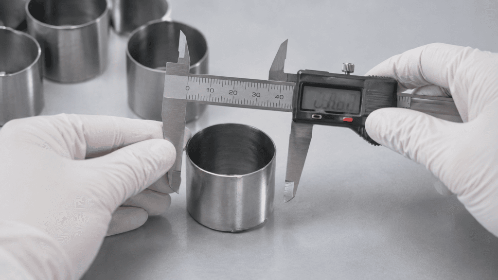
The final part should be evaluated against the approved drawing using methods appropriate for a thin-wall component.
Measurement planning should consider:
Instrument contact pressure
Measurement location
Number of orientations
Part support
Temperature
Instrument resolution
Operator consistency
One diameter reading is not sufficient to establish roundness.
For example, a crucible could measure 33 mm in one direction but show a different value after being rotated by 90 degrees. Measurements at multiple orientations may be needed where ovality is a concern.
Similarly, excessive caliper pressure can temporarily compress a thin wall and create a misleading result.
6. Controlled Handling and Packaging
The accepted part must remain protected after inspection.
Packaging design should account for:
Separation between crucibles
Protection of rims and walls
Prevention of radial compression
Prevention of part-to-part abrasion
Control of movement within the package
Clean inner wrapping
External impact protection
Export labeling and identification
A thin-wall batch should not be packed like thick machined discs or solid refractory-metal parts.
Critical Inspection and Acceptance Points
In the absence of publishable numerical inspection records, this case study does not claim an exact achieved tolerance, Cpk value, defect rate, or test result.
Instead, the following table identifies the acceptance characteristics most relevant to the project.
Inspection Area
What Should Be Evaluated
Why It Matters
Material identity
Grade, purity, sheet thickness, and documentation as agreed
Confirms the starting material matches the order
General appearance
Dents, cracks, burrs, surface contamination, handling marks
Confirms the joint is visually suitable for the agreed requirement
Outer diameter
Measurements at agreed locations and orientations
Indicates forming and shrinkage control
Inner diameter
Measurement using a suitable low-force method
Confirms internal geometry and wall relationship
Overall height
Measurement against the drawing
Indicates forming and assembly consistency
Inner height
Measurement where required by the drawing
Confirms usable internal depth
Roundness or ovality
Multiple circumferential orientations where specified
One diameter reading may not represent total geometry
Rim condition
Shape, edge quality, and local deformation
Important for handling and experimental use
Surface cleanliness
Visible residues, particles, staining, or contamination
Important for a research-oriented component
Packaging condition
Separation, support, and protection of thin walls
Preserves the accepted geometry during transport
Special inspections—such as helium leak testing, penetrant testing, radiography, metallography, chemical analysis, or third-party inspection—should only be claimed when they were agreed and documented for the order.
Approximately Three Weeks from Drawing to Export-License Processing
The project workflow took approximately three weeks from engineering drawing preparation through manufacturing and export-license processing.
A simplified public timeline is shown below.
Stage
Main Purpose
Requirement review
Confirm product geometry, quantity, material description, and confidentiality
Drawing preparation
Convert the requirement into a controlled manufacturing reference
Drawing confirmation
Ensure the customer and manufacturer use the same dimensional basis
Material and production preparation
Arrange suitable tantalum material and production planning
Fabrication
Form and join the thin-wall crucible structure
Acceptance activities
Review the completed parts against agreed requirements
Packaging
Protect the 0.5 mm walls and finished surfaces
Export documentation
Prepare the required export-license and shipment documents
Shipment preparation
Verify quantity, identification, and package condition
The three-week period should not be interpreted as a standard lead time for every tantalum crucible.
Lead time may change according to:
Material availability
Grade and purity
Dimensions
Quantity
Welded or seamless construction
Tolerances
Inspection requirements
Required documentation
Export classification
Destination
Packaging requirements
The value of this project timeline is not simply speed. It demonstrates the importance of coordinating engineering, manufacturing, quality, packaging, and export work as one project.
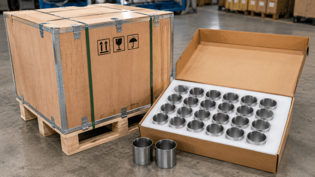
Packaging 100 Thin-Wall Tantalum Crucibles
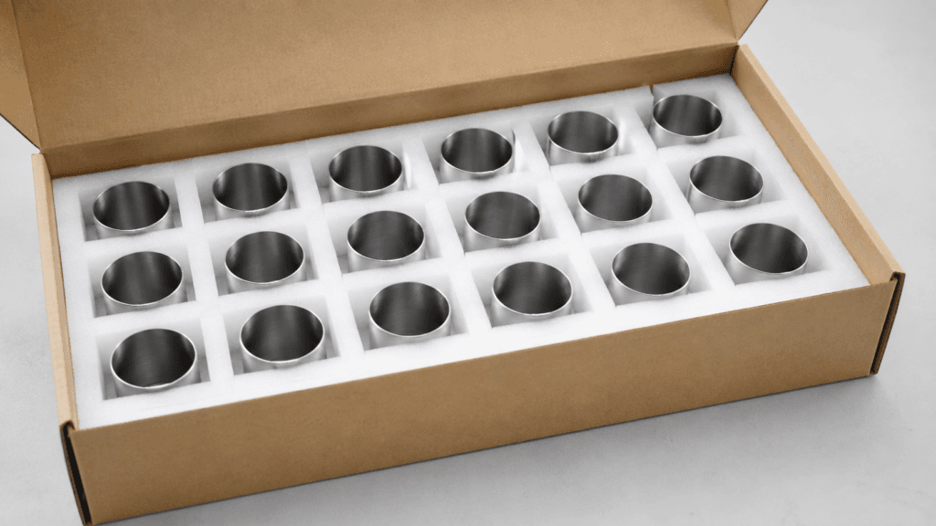
Packaging was a functional extension of dimensional control.
A suitable system needed to prevent the crucibles from:
Pressing against one another
Carrying the weight of the complete batch on their rims
Moving freely inside the carton
Rubbing against abrasive surfaces
Receiving radial compression
Collecting visible contamination
Being deformed by external impact
The recommended packaging concept for thin-wall refractory-metal components includes clean inner protection, separation between pieces, support that does not concentrate force on the wall, and a rigid outer package suitable for international transport.
Actual packaging photographs provide stronger evidence than generic text and should be included wherever available.
Project Significance
This project should not be reduced to a general statement that “MetalsTek can make tantalum crucibles.”
Its engineering value lies in the combination of:
A 0.5 mm nominal wall
Welded thin-sheet construction
High-purity tantalum
Compact dimensional requirements
A 100-piece quantity
Research-oriented use
Confidential customer requirements
An approximately three-week drawing-to-export workflow
The critical shift was from prototype feasibility to batch repeatability.
A single acceptable sample may be achieved through individual attention and correction. A batch of 100 pieces requires the manufacturing route to repeatedly manage forming geometry, joint fit-up, welding sensitivity, dimensional verification, handling, and packaging.
This distinction is relevant to laboratories and industrial buyers because a quotation should not be evaluated only on whether a supplier has previously made “a similar crucible.”
Buyers should also consider whether the supplier can manage:
Multiple pieces to one drawing
Revision control
Consistent material documentation
Thin-wall handling
Defined acceptance criteria
Batch packaging
Export documentation
Confidential project information
The entire batch—not merely one visually acceptable part—was the product.
Engineering Lessons from the Project
Prototype Success Does Not Automatically Prove Batch Capability
Prototype work can depend heavily on individual correction. Batch work requires repeatable inputs, stable process conditions, and consistent acceptance methods.
Welding Quality Begins Before Welding
Blank dimensions, edge preparation, forming, springback, and joint alignment all influence the welding stage. A welding operator cannot reliably compensate for uncontrolled variation in every formed body.
Dimensional Control Continues After the Weld
A continuous weld may still be associated with shrinkage, ovality, or local distortion. Weld appearance and dimensional acceptance must therefore be evaluated separately.
High Purity Must Be Defined
“High-purity tantalum” is useful as a public description, but a purchase order should specify the required grade, purity basis, impurity limits, and material documentation.
Thin-Wall Inspection Requires Care
The inspection method should not distort the component. Instrument pressure, support, measurement orientation, and acceptance criteria should be agreed in advance.
Packaging Is Part of Quality
A thin-wall component can leave the inspection area in acceptable condition and arrive damaged if the package transfers pressure to unsupported walls.
Repeatability Is a Manufacturing Capability
The ability to reproduce a controlled result across a batch is a separate capability from making one successful sample.
Frequently Asked Questions
Can tantalum be welded?
Yes. Tantalum can be joined using suitably controlled welding processes. The appropriate method depends on sheet thickness, joint geometry, part dimensions, equipment, shielding strategy, and acceptance requirements.
Why is thin tantalum difficult to weld?
The material must receive enough heat to establish the joint without burning through or excessively distorting the thin wall. Hot tantalum is also sensitive to atmospheric contamination, making joint cleanliness and shielding important.
Can 0.5 mm tantalum sheet be welded?
Published research has demonstrated TIG welding of 0.6 mm tantalum sheet, confirming that thin tantalum can be welded under controlled conditions. The welding parameters from a research study should not be copied directly to a different crucible geometry or production process.
What makes a batch of 100 crucibles harder than one prototype?
A prototype can receive individual adjustment. A 100-piece order requires repeatability in blank preparation, forming, fit-up, welding, dimensional verification, handling, and packaging.
Does “100 identical crucibles” mean there is no dimensional variation?
No manufactured parts are literally identical at every measurement point. The technically correct requirement is that the 100 crucibles are manufactured to the same approved drawing and remain within the agreed acceptance limits.
Why can welding affect crucible roundness?
The heated and molten region contracts during cooling. On a thin cylindrical wall, localized contraction can contribute to ovality, flattening, or a change in diameter near the joint.
Is a welded tantalum crucible suitable for high-temperature experiments?
It may be suitable when the material, joint construction, temperature, atmosphere, sample chemistry, and acceptance requirements match the experiment. The end user must confirm compatibility with the actual operating conditions.
Can tantalum crucibles be used in high-temperature air?
Tantalum becomes increasingly reactive with oxygen at elevated temperatures. High-temperature applications commonly require a suitable vacuum or controlled atmosphere, depending on temperature and exposure time.
What should be inspected on a thin-wall welded crucible?
Typical acceptance points include material identity, weld appearance, OD, ID, height, roundness where specified, rim condition, surface cleanliness, and packaging condition. Additional testing must be agreed before production.
What information is required for a custom tantalum crucible quotation?
Explore material selection, dimensional stability, thermal performance, and custom component requirements for vacuum furnaces, crystal-growth systems, and other demanding high-temperature equipment.
Review refractory-metal, ceramic, and graphite crucibles and boats used in evaporation, laboratory research, metallurgy, crystal growth, and high-temperature materials processing.
Review available tantalum sheet and foil grades, thickness ranges, material standards, surface conditions, and customization options for fabricated tantalum components.
This ASTM standard covers unalloyed tantalum and selected tantalum alloys supplied as plate, sheet, and strip. It should be referenced as general material-standard context unless the project documents specifically confirm ASTM B708 compliance.
This study examines TIG welding of 0.6 mm tantalum sheet and supports the article’s discussion of thin-sheet weldability, oxidation, shielding, and heat-affected-zone behavior.
This research evaluates how atmospheric impurities—including air, oxygen, nitrogen, and hydrogen—can influence tantalum weld hardness, ductility, and joint integrity.
Use this government source for general background on tantalum as a strategic refractory metal rather than for project-specific purity or performance claims.
Replace the brackets with natural MetalsTek internal links before publication.
Discuss Your Thin-Wall Tantalum Project
Thin-wall tantalum fabrication requires more than selecting a refractory metal and applying a welding process.
The engineering drawing, material requirement, forming geometry, joint design, dimensional acceptance, quantity, documentation, and packaging must be reviewed together.
MetalsTek supports custom tantalum crucibles and fabricated tantalum components for laboratory research, vacuum systems, high-temperature materials processing, and specialized industrial projects.
For technical review and quotation, please send:
Your drawing
Required tantalum grade or purity
Critical dimensions and tolerances
Quantity
Intended operating atmosphere
Inspection requirements
Documentation requirements
Delivery destination and schedule
Contact sales@metalstek.com to discuss manufacturability, lead time, and quotation requirements.
Technical References
ASTM B708-25, Standard Specification for Tantalum and Tantalum Alloy Plate, Sheet, and Strip.
Weld Joint of Tantalum Sheet by Tungsten Inert Gas Welding, reporting TIG welding research on 0.6 mm tantalum sheet.
Microstructure of Tantalum Sheet Welded Joint by Argon Tungsten Arc Lap Welding.
Electron-Beam Versus TIG Welding of Niobium and Tantalum, examining welded tantalum joints under different atmospheric impurity conditions.
Have a similar engineering requirement?
Send us your drawing, material requirement, quantity, and critical specifications. Our engineering team can review manufacturability and quotation requirements.
MetalsTek completed and shipped three Lu-based multicomponent oxide target formulations. This case compares their nominal compositions and explains the manufacturing considerations behind a custom research order.