MetalsTek Engineering Guide
The challenge of large ceramic targets
A large ceramic sputtering target has to survive manufacture, installation and repeated heating during deposition. Brittle target bodies can chip during machining or handling. During sputtering, uneven heating and differences in expansion between the ceramic and its backing plate can create stress. Bonding supports heat transfer, but it does not eliminate thermal-shock risk.[1][6]
In powder-derived ceramics, uneven packing and sintering shrinkage can cause distortion or cracks. The proposed geometry also needs allowance for finishing operations such as grinding or polishing.[8]
The practical size limit depends on the material, manufacturing route and required geometry. A design feasible in one oxide may be difficult in another. Lithium phosphate (Li₃PO₄), ITO and IGZO are useful examples of ceramic target families; their forming, densification and machining requirements need separate review. MetalsTek’s ITO and IGZO target options illustrate that range of compositions.
For segmented ceramic sputtering targets, the engineering task includes tile arrangement, joint clearances, backing plate interfaces and the bond beneath each tile.
Single-piece vs. segmented targets
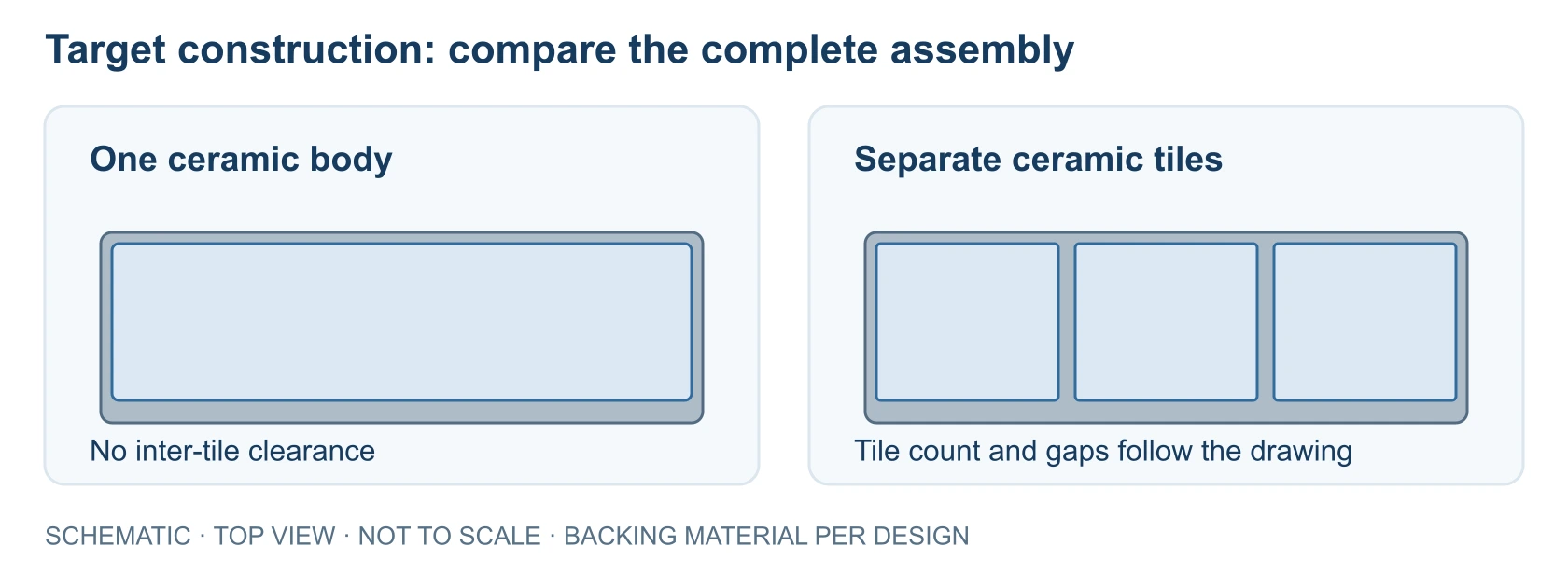
A single-piece target has one ceramic body. A segmented target has separately manufactured tiles arranged to form the required sputtering surface. Both constructions may use a bonded backing plate.
Consider segmentation when the requested envelope challenges the supplier’s material-specific manufacturing or handling capability. It is useful only if the cathode can accommodate the resulting joints and assembly. Neither lower cost nor better reliability follows automatically from using smaller pieces.
| Factor | Single-piece | Segmented |
|---|---|---|
| Manufacturing feasibility | Depends on material, dimensions and production route. | May enable some larger designs using smaller tiles. |
| Assembly complexity | No inter-tile positioning. | Requires tile positioning and joint control. |
| Handling risk | Assess the complete ceramic body’s geometry and fragility. | Assess individual tiles and the assembled target. |
| Joint considerations | No segmentation joints. | Specify seam geometry, location and clearances. |
| Backing plate | Bonding or mounting arrangement depends on the cathode. | Coordinate tile layout, bonding and plate support. |
Compare proposed constructions against the same equipment drawing and acceptance criteria. The sputtering target catalogue is a starting point for material and form enquiries; final feasibility needs drawing review.
Joint geometry: straight vs. beveled
Straight butt joints
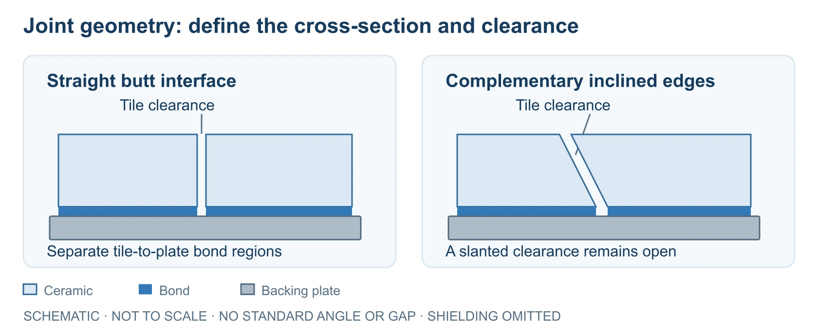
A straight butt interface has opposing edges perpendicular to the sputtering face, separated by a designed clearance. Specify the tile-to-tile clearance separately from the bondline thickness between each tile and the backing plate. Clearance must account for assembly tolerances and differential thermal expansion. Too little space can allow edge contact; an opening also requires assessment of possible exposure of the backing or bond material.[1]
Complementary beveled joints
Beveled interfaces use matching inclined edges. The drawing must show the complete section: a small edge chamfer is a different feature. Inclination changes the path through the joint and may affect access to underlying material. A simple slanted gap does not provide the same shielding as a stepped or labyrinth path.[2]
For either design, define alignment datums, permissible height differences at the sputtering face and edge condition. Review seam positions against the equipment’s expected erosion pattern, and check how the joint section changes over the intended usable target thickness. Slender ceramic edges also need a machining and handling assessment.
A bevel alone does not establish improved film uniformity; that requires evaluation in the deposition system.
Backing plate selection
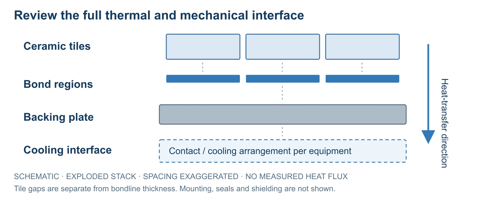
A backing plate provides mechanical support and a path for heat toward the cathode cooling system. Copper is common because of its thermal conductivity, and OFHC copper backing plates are one available option. Other plate materials are used; copper is not the only solution for ceramic targets.[5][7]
Selection should consider expansion compatibility and plate stiffness alongside heat conduction. Plate bowing, cooling contact and mechanical loading affect the assembly. Cooling-water pressure matters where the plate is part of a pressurized cooling boundary.[5]
Confirm the mounting pattern, seal locations, cooling configuration and permitted assembly thickness against the source drawing. These interfaces can constrain the target even when the ceramic itself is manufacturable. For segmented designs, check support beneath every tile and the relationship between seams and mounting features.
Bonding methods and selection factors
Indium bonding
Indium provides a conductive metallic interface. Its softness can accommodate some differential movement between the target and plate. Selection requires compatible surfaces and a qualified operating envelope. The bond’s temperature limit remains relevant even when the ceramic can withstand hotter conditions.[3]
Elastomer bonding
Engineered elastomer bonds offer another route for selected assemblies, including some fragile or temperature-sensitive materials. Their properties depend on the formulation and bonding process. Ask about vacuum suitability, thermal behavior, electrical properties where relevant, and the preparation or cure cycle. A rating for one formulation cannot be assigned to all elastomers.[4]
Review either method against the complete geometry, service conditions and contamination requirements. Specify acceptable bond coverage and how it will be assessed, together with any reporting requirement. In a segmented assembly, distinguish bonding each tile to the plate from filling the tile-to-tile joint. Any masking or exclusion of bond material near a seam must be defined in the assembly design.
Request a target bonding review to discuss these constraints before selecting a method.
Engineering checklist before ordering
A useful RFQ describes the ceramic and its interfaces with the sputtering source. Send a dimensioned drawing with revision, units and datums, plus the assembly drawing if bonding is required.
| Requirement | Information to confirm |
|---|---|
| Material | Composition, purity basis and required documentation. |
| Dimensions | Length, width, thickness, tolerances and surface requirements. |
| Target construction | Single-piece or segmented; proposed tile layout. |
| Joint geometry | Straight, beveled or drawing-defined; gap and height requirements. |
| Backing plate | Material, dimensions, cooling and mounting features. |
| Bonding | Requested method, operating conditions and inspection requirements. |
| Equipment | Source model and mounting or interface drawing. |
| Quantity | Prototype or production quantity, with required delivery. |
Ask the supplier to identify drawing exceptions before quotation approval. Final construction should follow equipment requirements and confirmed manufacturing feasibility. Keep requirements distinct from measured acceptance results.
A practical engineering example
A large rectangular lithium phosphate ceramic target may require evaluation of segmented construction, joint geometry and backing plate compatibility. An engineer would first establish the cathode envelope and material requirements, then ask the supplier to assess a single body against a tiled alternative.
If tiles are proposed, the review would include their orientation, clearances, face alignment and bonding compatibility. A separate section drawing would define any inclined interface. Material-specific preparation and service limits would also need confirmation.
This is a generic selection example, with no assumed dimensions, fabrication route or test outcome. The same review sequence can inform other ceramics, with each material assessed separately.
Frequently asked questions
Does every ceramic need the same segmentation plan?
No. Material properties, feasible tile dimensions, machining and cathode geometry differ. A layout suitable for one composition may be unsuitable for another.
What sets a feasible one-piece size?
The material and production route, available equipment, finished geometry and acceptance requirements. There is no universal maximum dimension covering all ceramic targets.
Is a bevel a substitute for specifying the joint gap?
No. Define the section and clearance together, including tolerances, alignment and the usable erosion condition. Neither the word “beveled” nor a nominal angle describes the complete interface.
Can several tiles share one backing plate?
Yes, documented designs use a common plate. Its support, cooling and mounting interfaces must suit the complete assembly; sharing a plate does not establish suitability by itself.
What belongs in the quotation drawing pack?
Include ceramic detail drawings, tile layout and joint sections, plate and source interfaces, material requirements, bonding conditions and quantity. Mark unresolved features for review.
Need Engineering Support for a Large Ceramic Sputtering Target?
Send MetalsTek your material, target dimensions, equipment drawings, joint requirements, backing plate details, bonding requirements and quantity. Identify fixed equipment interfaces and features open to supplier review so the quotation can address a feasible assembly.
Technical sources
Patents document design approaches and manufacturing concerns; their examples are not universal specifications, validated MetalsTek results or a claim of use of the patented processes.
[1] JX Nippon Mining & Metals, JP7311290B2. Segmented ceramic assemblies, clearance and underlying-material exposure.
[2] Applied Materials, US20060266639A1. Disclosed straight, complementary inclined and stepped interfaces.
[3] Kurt J. Lesker, Indium Target Bonding Service. Conductive metallic bonding, compliance and service limitations.
[4] Kurt J. Lesker, Elastomer Target Bonding Service. Formulation-specific compatibility and bonding-process considerations.
[5] Materion, Choosing Appropriate Backing Plates. Thermal path, support, loading and plate deformation.
[6] Kurt J. Lesker, Why Is My Sputtering Target Breaking?. Material-dependent cracking, thermal shock and cooling.
[7] Materion, PVD Thin Film Consumables. Multiple backing materials and mechanical/thermal roles.
[8] Heraeus, US20080210555A1. Qualitative powder-formed ceramic packing, shrinkage, distortion and finishing concerns.