Jump to:Introduction1. Project Overview2. Product Specifications3. Manufacturing Challenges4. Manufacturing & Inspection5. Reported Result6. Buyer RFQ Checklist7. Material Selection8. FAQ
Introduction
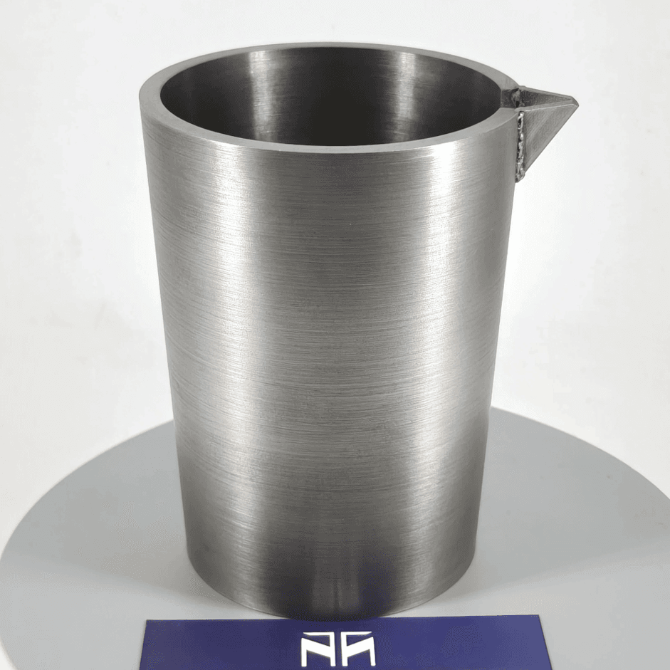
Tungsten crucibles are selected for processes in which ordinary metals cannot maintain dimensional or chemical stability at high temperature. Yet manufacturing difficulty depends as much on geometry as on material.
In this project, MetalsTek received a customer drawing for a custom conical tungsten crucible with a welded transfer spout. The body required a top outer diameter of Ø73 mm, a bottom outer diameter of Ø63 mm, a height of 100 mm, a 4 mm wall, a 4 mm bottom, and an R10 internal bottom radius. The spout then had to be positioned and joined without introducing visible cracking, unacceptable distortion, or misalignment.
The central engineering problem was therefore not simply how to machine tungsten. It was how to keep a relatively thin, tapered tungsten body stable through cavity machining, spout fit-up, localized welding heat, and final inspection. This case study follows that manufacturing sequence and explains the controls used at each risk point.
1. Project Overview
The customer required a drawing-based tungsten crucible for high-temperature service. The proprietary application and detailed spout geometry are not disclosed, but the component had to combine the following features in one finished assembly:
- Conical tungsten body
- Controlled 4 mm wall thickness
- 4 mm bottom thickness
- R10 internal bottom radius
- Welded tungsten pouring or transfer spout
- Final dimensional and visual verification
Potential use environments for this type of component include vacuum furnaces, laboratory melting systems, crystal-growth-related equipment, and controlled high-temperature material transfer. Final suitability still depends on the operating temperature, atmosphere, processed material, and acceptance criteria defined for the actual order.
Related product information is available on the MetalsTek tungsten crucibles page.
2. Product Specifications
The following requirements were taken from the customer drawing or the agreed case-study scope. Where the source record does not disclose an exact value, the limitation is stated rather than estimated.
| Parameter | Specification / Project Note |
| Material | Tungsten |
| Material purity | High-purity tungsten; the exact purity should follow the approved quotation or order |
| Product type | Conical tungsten crucible with welded spout |
| Top outer diameter | Ø73 mm |
| Bottom outer diameter | Ø63 mm |
| Overall height | 100 mm |
| Wall thickness | 4 mm |
| Bottom thickness | 4 mm |
| Internal bottom radius | R10 mm |
| Spout type | Welded tungsten pouring / transfer spout |
| Spout geometry | Manufactured according to the approved customer drawing; dimensions not publicly disclosed |
| Tolerance | According to the customer drawing |
| Surface condition | Machined surface with final visual inspection; special polishing or cleaning requires prior agreement |
| Inspection scope | Dimensional checks, wall and bottom thickness verification, surface inspection, spout alignment review, and weld-area visual inspection |
| Leak or pressure testing | Not claimed unless specifically required, performed, and documented for the order |
| Manufacturing route | Drawing review, staged machining, spout fit-up and joining, post-weld inspection |
The part was not large by heavy-furnace standards, but size alone does not determine manufacturing complexity. A compact refractory-metal part can still be difficult when it combines a deep cavity, changing wall profile, narrow remaining wall, internal radius, and a welded attachment.
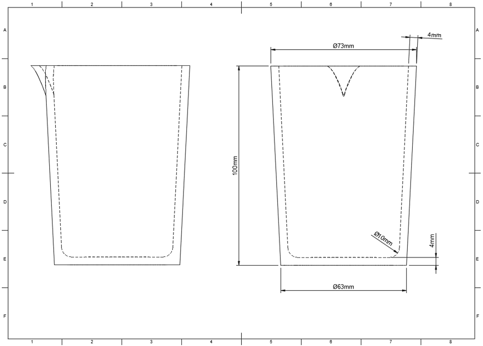
Anonymized customer drawing showing the conical profile, 4 mm wall and bottom thickness, and R10 internal radius.
3. Why the Part Was Difficult to Manufacture
| Risk Area | Why It Matters | Required Control |
| Thin-wall conical body | The tapered cavity reduces rigidity as material is removed; tungsten is also vulnerable to chipping and stress-related damage | Staged machining, stable support, conservative material removal |
| Wall and bottom geometry | Top diameter, bottom diameter, taper, wall, bottom, and R10 radius must remain consistent as one geometry | In-process checks before irreversible finishing steps |
| Welded spout | Localized heat can disturb a body that has already been machined close to final dimensions | Fit-up, positioning, controlled joining, and post-weld verification |
Challenge 1: Machining the Thin-Wall Conical Body
The internal cavity could not be treated like a straight cylindrical bore. The outer profile changed from Ø73 mm at the top to Ø63 mm at the bottom, while the cavity had to leave a nominal 4 mm wall and form the R10 internal bottom radius.
As the cavity became deeper, the remaining section became less rigid. Excessive cutting force, unstable support, vibration, or an aggressive finishing pass could produce edge chipping, local wall variation, surface damage, or crack initiation. These risks matter in service because a local defect or thin area can become a stress concentration during heating and cooling.
Solution: Sequence the Machining Around Remaining Wall Strength
The drawing was reviewed as a manufacturing sequence rather than only as a set of final dimensions. The body was formed progressively so that sufficient support remained while the internal profile was developed. The project approach emphasized:
- Establishing the external reference geometry before the wall became thin
- Removing internal material in controlled stages rather than forcing the final cavity in one step
- Maintaining stable support as the cavity depth increased
- Reducing vibration and concentrated force near the top edge and thin-wall zones
- Forming the R10 bottom transition without leaving a sharp stress concentration
- Preserving enough geometric stability for the later spout-joining operation
The source material does not provide machine settings, tool grades, or pass depths, so no numerical process parameters are claimed here. Those values should remain part-specific and controlled within the production traveler or work instruction.
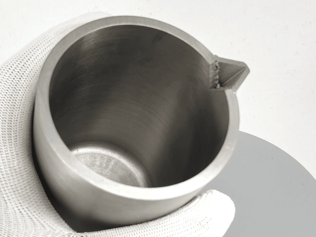
Top view of the machined cavity, wall section, internal bottom transition, and welded spout.
Challenge 2: Maintaining Wall Thickness and Final Geometry
The drawing could not be accepted by checking overall height alone. The functional geometry depended on the relationship among top diameter, bottom diameter, taper, wall thickness, bottom thickness, internal radius, and final spout position.
A conical wall also makes measurement more demanding because the profile changes continuously. A part may meet both end diameters yet still contain local wall variation or an incorrect internal contour. For that reason, inspection had to be introduced before the final machining and joining steps made correction difficult.
Solution: Treat Measurement as a Manufacturing Step
Critical features were checked during production and then reviewed again after welding. The control logic was:
- Confirm external reference diameters and height
- Check wall and bottom thickness before final finishing
- Review the conical profile rather than relying only on the two end diameters
- Verify the R10 internal bottom transition
- Confirm that the machined body remained suitable for spout fit-up
- Repeat relevant dimensional checks after welding to identify joining-related movement
This process-stage approach reduces the risk of discovering a non-correctable geometry problem only after the spout has been joined.
Challenge 3: Joining and Aligning the Tungsten Spout
The spout was the highest-risk feature because it converted a machined crucible into a joined assembly. The joint had to be located according to the drawing, mechanically stable, visually free from cracking, and aligned with the intended transfer direction.
Localized heating can create a steep temperature gradient between the weld area and the surrounding tungsten body. On a relatively thin conical wall, uncontrolled heat or poor fit-up can cause local distortion, crack initiation, an uneven transition, or a spout direction that no longer matches the drawing.
| Joining Risk | Possible Consequence |
| Poor fit-up | Uneven joint geometry or localized stress concentration |
| Excessive or concentrated heat | Distortion of the adjacent crucible wall |
| Insufficient restraint or positioning | Spout angle or location outside the intended geometry |
| Inadequate post-weld review | Visible defects or dimensional movement left unidentified |
Solution: Control Fit-Up Before Heat Is Applied
The spout was handled as a precision joining feature, not as a secondary accessory. The manufacturing sequence focused first on fit-up and position, then on heat control, and finally on post-weld verification:
- Prepare and visually review the mating area
- Check spout-to-body contact and location against the drawing
- Use stable support to maintain the intended orientation during joining
- Avoid unnecessary heat concentration near the thin-wall section
- Inspect the weld transition for visible cracking, poor connection, or local distortion
- Recheck spout alignment and the affected body dimensions after welding
The available project record does not identify the welding process, shielding conditions, preheat temperature, or heat-input values. They are therefore not specified in this article. For future orders, any process qualification, leak testing, or additional nondestructive examination should be agreed before production.
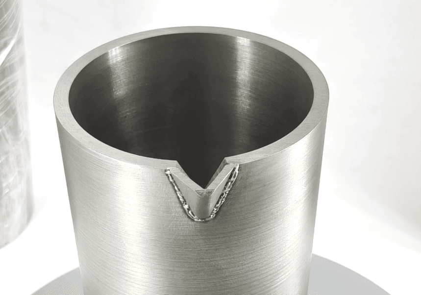
Welded tungsten spout and adjacent transition area after joining and visual inspection
4. Manufacturing and Inspection Route
The practical workflow kept each control point close to the operation that created the corresponding risk.
| Stage | Primary Objective | Main Risk | Verification Focus |
| Drawing review | Define geometry and acceptance scope | Unclear tolerances or unreviewed special features | Wall, bottom, radius, spout position, inspection requirements |
| Body machining | Produce the outer profile and cavity | Chipping, wall variation, taper or radius deviation | Diameters, height, profile, wall and bottom thickness |
| Spout fit-up and joining | Create the functional transfer feature | Misalignment, thermal stress, local distortion | Fit-up, position, visible weld condition |
| Final inspection | Confirm the completed assembly | Joining-related dimensional movement or surface defects | Drawing comparison, surface, spout alignment, weld area |
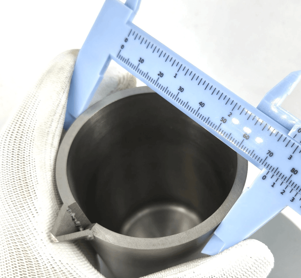
Dimensional check of the completed crucible opening after spout joining.
5. Reported Project Result
The source record reports that the completed component achieved the required conical structure, welded spout, controlled wall and bottom geometry, finished internal cavity, and final dimensional verification. The following matrix distinguishes reported checks from tests that were not claimed.
| Inspection Item | Acceptance Basis | Reported Outcome |
| Overall dimensions and conical geometry | Customer drawing | Verified according to the drawing |
| Wall and bottom thickness | Drawing requirements | Controlled and verified within the project inspection scope |
| Spout location and alignment | Customer drawing | Reviewed after joining |
| Weld transition and adjacent surface | Visual inspection | No visible cracks identified; transition finished and inspected |
| Surface condition | Agreed machined condition | Final visual inspection completed |
| Vacuum leak or pressure tightness | Only if separately specified | Not claimed in this case study |
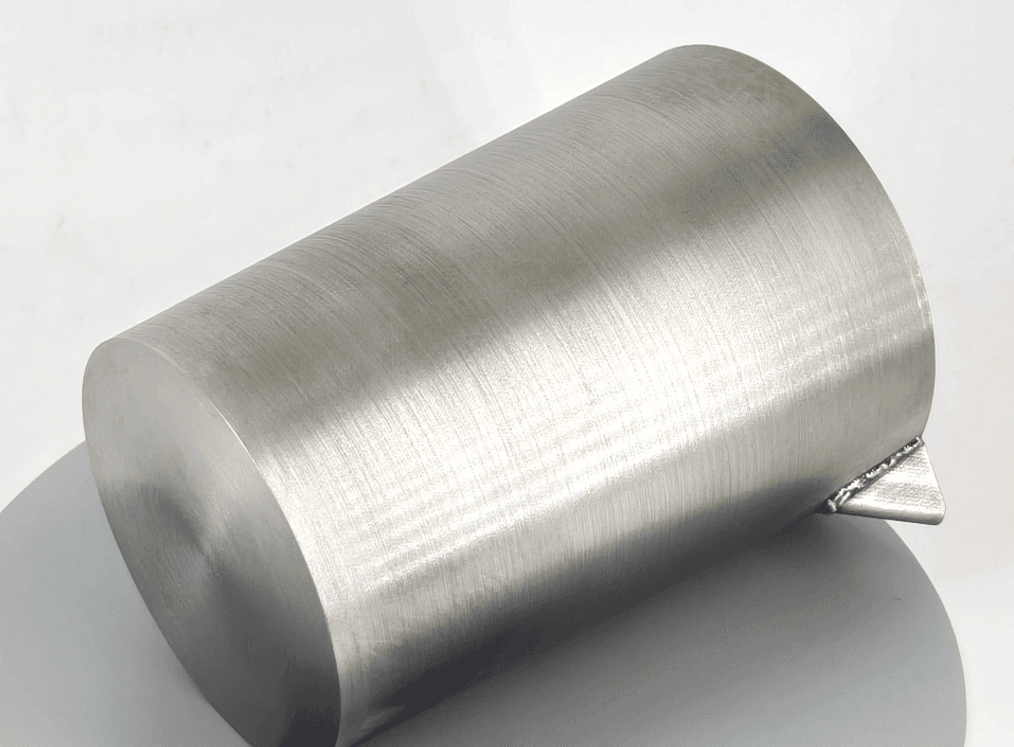
Side and bottom view of the machined conical crucible body.
These outcomes show why custom tungsten crucibles are not only material-supply items. Success depends on coordinating design review, machining sequence, joining preparation, geometry control, and inspection. The customer remains responsible for final application validation under the actual operating temperature, atmosphere, thermal cycle, and processed material.
6. What Buyers Should Define Before Quotation
A complete RFQ reduces uncertainty and allows the manufacturer to evaluate feasibility before material is committed.
| Information Required | Why It Matters |
| Drawing or CAD file | Defines geometry, tolerances, datum references, and special features |
| Tungsten purity or grade | Controls contamination requirements and material sourcing |
| Top and bottom diameters, height | Defines the basic conical envelope |
| Wall and bottom thickness | Directly affects rigidity, machining risk, and thermal response |
| Internal radius and cavity profile | Affects tool access, stress concentration, and inspection |
| Spout size, angle, location, and joining area | Determines fit-up, alignment, and joining difficulty |
| Surface finish and cleaning requirements | Defines finishing and acceptance scope |
| Operating temperature and atmosphere | Supports suitability and oxidation-risk review |
| Processed material | Supports chemical-compatibility review |
| Quantity | Affects tooling, production route, and cost |
| Inspection and documentation | Clarifies dimensional reports, CoA, special testing, or third-party inspection |
For welded refractory-metal components, acceptance criteria should be defined before production. Requirements such as leak testing, dye penetrant testing, radiography, sectioning, weld qualification, special cleaning, or third-party inspection are not automatic and should be included in the quotation scope when needed.
7. Why Tungsten Was Selected Instead of Other Crucible Materials
Molybdenum can be easier to fabricate and may be more economical for some high-temperature applications. Tantalum and graphite also offer useful properties in selected environments. The correct choice, however, depends on more than melting point.
| Material | Main Advantage | Important Limitation |
| Tungsten | Very high temperature stability and low vapor pressure | More difficult to machine and join; oxidation must be controlled |
| Molybdenum | Lower fabrication difficulty and good high-temperature capability | Lower maximum temperature capability than tungsten |
| Tantalum | Useful corrosion resistance and good fabricability in selected designs | Compatibility with the processed material must be checked |
| Graphite | Good thermal-shock resistance and comparatively easy machining | May be unsuitable for contamination-sensitive or reactive processes |
In this project, the customer specified tungsten for a severe high-temperature application requiring the crucible to retain its geometry. Selection for another project should consider atmosphere, processed material, contamination tolerance, thermal cycling, geometry, and manufacturability together.
For alternatives, review MetalsTek’s molybdenum crucibles and boats and broader refractory metals product range.
8. Search-Intent FAQ
The questions below reflect common buyer and engineering search intent. They are not presented as verified Google “People Also Ask” questions unless separately confirmed from a live search-results review.
1. What is a tungsten crucible used for?
Tungsten crucibles are used in selected vacuum, inert-atmosphere, melting, thermal-processing, evaporation, and crystal-growth-related systems where high-temperature dimensional stability and low vapor pressure are important. Final suitability depends on chemical compatibility and operating conditions.
2. Why is tungsten suitable for very high temperatures?
Tungsten combines an extremely high melting point with low vapor pressure and good resistance to deformation at elevated temperature. These properties can be valuable when common metals would soften, evaporate, or contaminate the process.
3. How are tungsten crucibles manufactured?
Manufacturing routes may include powder metallurgy, sintering, forging, spinning, machining, or combined fabrication. The selected route depends on size, density, wall thickness, geometry, tolerance, and whether the part includes welded or machined special features.
4. Why are thin-wall tungsten crucibles difficult to machine?
Removing the internal cavity reduces section rigidity. Because tungsten is hard and relatively brittle at room temperature, unstable support, vibration, or concentrated cutting force can lead to chipping, local wall variation, surface damage, or cracking.
5. Why is a conical crucible harder to control than a straight cylindrical one?
A conical crucible has a continuously changing profile. The manufacturer must control both the outer taper and inner cavity while maintaining the specified remaining wall, bottom geometry, and internal transition radius.
6. Can tungsten components be welded?
Yes, but tungsten joining is demanding. Joint preparation, fit-up, alignment, heat control, shielding or atmosphere, and post-weld inspection must be selected for the specific design and service requirement.
7. Why can tungsten crack during welding?
Localized heating and cooling can create high thermal gradients and residual stress. Thin sections, poor fit-up, contamination, restraint conditions, and inappropriate heat input can increase cracking risk.
8. How can spout distortion be reduced?
The spout should be fitted and positioned before joining, supported in the required orientation, and checked again after welding. The joining sequence should avoid unnecessary heat concentration in the adjacent thin wall.
9. What is a tungsten crucible with a spout used for?
A spout supports controlled pouring, transfer, or directional discharge. Its angle, opening, location, and alignment should match the equipment interface and the behavior of the processed material.
10. Are tungsten crucibles suitable for vacuum furnaces?
They can be suitable because of tungsten’s high-temperature stability and low vapor pressure. The buyer must still define temperature, vacuum level, atmosphere, thermal cycle, processed material, and cleanliness requirements.
11. Can tungsten crucibles be used for crystal growth?
They are used in selected high-temperature growth systems. Purity, density, geometry, surface condition, thermal-field requirements, and interaction with the charge material should be reviewed for each process.
12. Can tungsten crucibles hold molten metals?
They can hold selected metals and high-temperature materials, but chemical compatibility must be evaluated. Reactive melts, rare-earth materials, and special alloys may require application-specific review.
13. Is visual weld inspection enough?
Visual inspection can identify surface cracking, poor transition, misalignment, and obvious distortion, but it does not prove leak tightness or internal weld integrity. Additional testing must be specified when the application requires it.
14. What information is needed for a custom quote?
Provide the drawing, material purity, dimensions, tolerances, wall and bottom thickness, spout geometry, surface and cleaning requirements, operating conditions, processed material, quantity, and inspection requirements.
15. Why use a custom manufacturer rather than a standard crucible supplier?
A custom manufacturer can review drawing feasibility, machining sequence, thin-wall risk, welded features, inspection access, and application-specific documentation instead of limiting the project to fixed sizes and simple shapes.
Need a Custom Tungsten Crucible?
Custom tungsten crucibles require coordinated control of material, geometry, machining stress, welded features, and inspection. A detailed drawing and clearly defined acceptance criteria allow technical risks to be reviewed before production.
MetalsTek Engineering supplies tungsten crucibles and drawing-based refractory-metal components for demanding high-temperature applications. For a manufacturability review and quotation, send:
- Drawing or CAD file
- Tungsten purity requirement
- Diameters, height, wall thickness, bottom thickness, and internal radius
- Spout dimensions, angle, position, and joining requirements
- Operating temperature and atmosphere
- Processed material
- Quantity
- Inspection, documentation, cleaning, and packaging requirements
Related engineering considerations are also discussed in MetalsTek’s precision components for vacuum furnaces and crystal growth systems resource.